Pertronix Electronic Ignition Fitted to a Rover P6B
 Stan Barnes, signing as "vaultsman" on the Classic Rover Forum based in the UK, installed a Pertronix Electronic Ignition into his Rover P6B RHD automobile. In an email discussion between Stan and Eric (the RCCC Webmaster), Stan offered to fill the gap in the RCCC coverage of electronic ignitions in Rovers. He offered his photos and instructions as he posted them to the forum. In the spirit of sharing and helping, Stan has presented his information below. "Roly", another member of the Classic Rover Forum gave permission for his findings to be also noted in Stan's article.
Bright & sunny Saturday...if a little brass-monkey...perfect time to test one's circulation with the bonnet up!
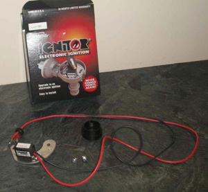
This is what I got for my 60 quid...not sure what the bit of Perspex was meant to be for!
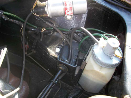
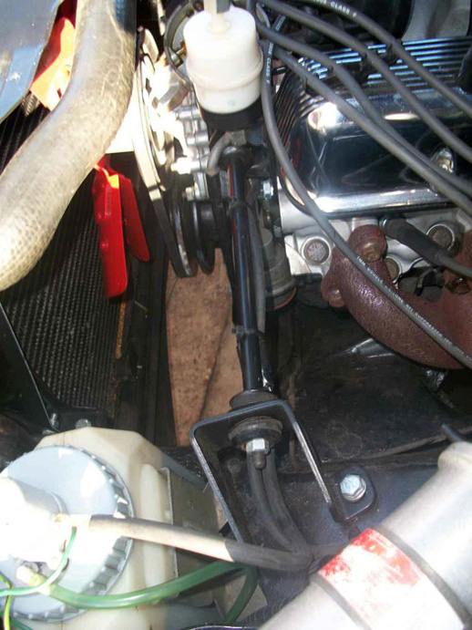
Starting point:
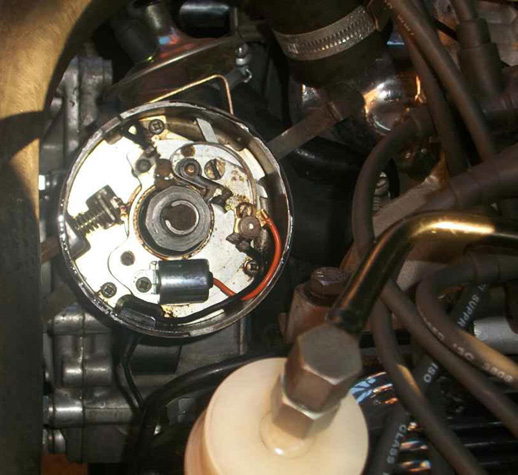
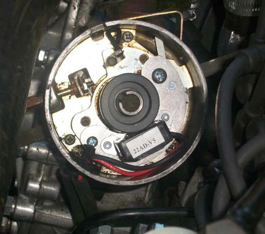
Dwell is preset with the Ignitor so, as well as the points and condenser, the dwell adjuster spring comes out and the screw's tightened as far as it will go. And yes, I managed to avoid dropping the locknut into the guts of the dizzy! :) Hardest bit though was getting the LT lead grommet/hard plastic *?;$=+%! free from the distributor body...Lucas certainly didn't mean that to fall out.
Module in...
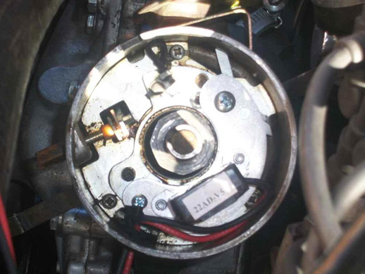
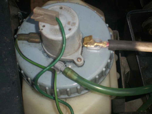
The red lead from the Ignitor module needs a 12V supply, either from the +ve terminal of an unballasted coil or, in my case, courtesy of the Trico washer pump via a piggyback Lucar terminal soldered on to replace the ring terminal that the module came with.
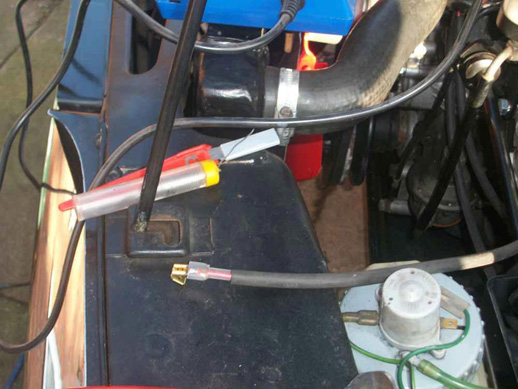
The rubber sleeves are my additions..the Ignitor cables are actually quite slender - 20 AWG = (AFAIK) 0.5 sq.mm.)
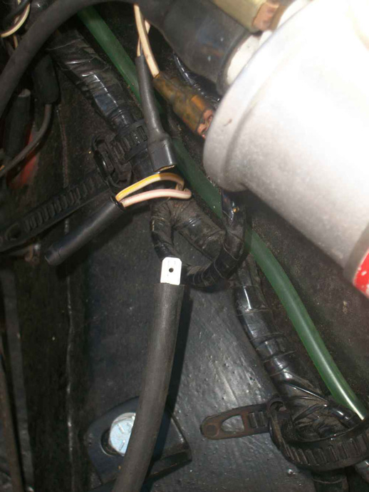
Black Ignitor cable to be connected to the coil -ve according to the Pertronix instructions...but no. In my case ('73 Series 2) coil -ve connection is a White/Slate cable that runs up to the tacho and the return is a White/Black cable that originally ran to the distributor via a handily-sited Lucar connector. So...black Ignitor cable connects here. (The Pink/White cable in the centre of the pic is the infamous (and often elusive) ballast resistor)
Cables sorted.
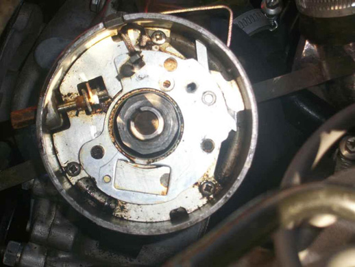
Magnet sleeve fitted to the dizzy shaft...
Roly wrote:The only problem I found & something to look out for, is that the magnetic trigger that fits over the cam lobes had the caused the rotor arm to be raised up enough that the cap was sitting on the rotor & not the distributor. Whilst checking the timing I noticed the cap had taken on a sort of rotating undulation! The few minutes of running like this created enough friction to render the cap u/s. When I checked the rotor arm with a couple of spare ones, I found that they all varied in depth. I ended up trimming a bit off of the bottom of one to ensure I had enough clearance.
..and I had to trim about 20 thou off the bottom of the rotor to get the dizzy cap sitting down nicely. Thanks for the tip Roly!
So...all set to go. Engine fired up sweetly on the second turn of the key and felt eager and responsive whilst warming up. And I had to take about 50 rpm out of the idle speed to get back down to 650 once warmed up. A good sign!
Timing checked and was still spot on at the 8 deg. BTDC I'm running at idle with vacuum disconnected.
Road Test! Blimey...ran like a dream. So smooth and no sign of pinking providing I stir the box as normal. Only intended to nip down to the local factors for some antifreeze...but found myself putting 30 miles on the clock.
All in all I'd have to say..so far..this is probably the best 60 quid I've spent on Occie to date. Highly recommended!
This is the relevant bit of my wiring diagram by the way:
Distributor - 22
Tacho - 37
Coil - 44
Ballast - 45
In a discussion about a piece of Perspex found in the kit, it was suggested that it might be a gap measuring tool. Stan noted:
There's no mention of it at all in the instructions but from a quick browse around the net, you're right I think. It seems though that the gap's not critical - anywhere from 10 to 75 thou will work OK and variations won't affect the dwell.d There's no gap adjustment provided on the module mounting plate anyway though - the 2 screws go through exact size holes to hold it to the baseplate.
I've just been out and checked my gap at 18 thou, the Perspex measuring 32 thou.
A further discussion on Stan's wiring diagram vis a vis other wiring variations caused Stan to note:
According to the WM it seems the change point was for chassis suffix D for the 3500 and C for the 3500S (mine's an S and suffix C). Might not be as clear-cut as that though!